PRODUCT OVERVIEW
The FM broadcast band (88–108 MHz) and the lower VHF airband (108–118 MHz) occupy one of the busiest and most interference-prone regions in the radio spectrum. AM broadcast transmitters below 30 MHz, shortwave stations, paging systems, and an increasingly crowded VHF environment above 130 MHz all compete for the dynamic range of any wideband receiver tuned to this region.
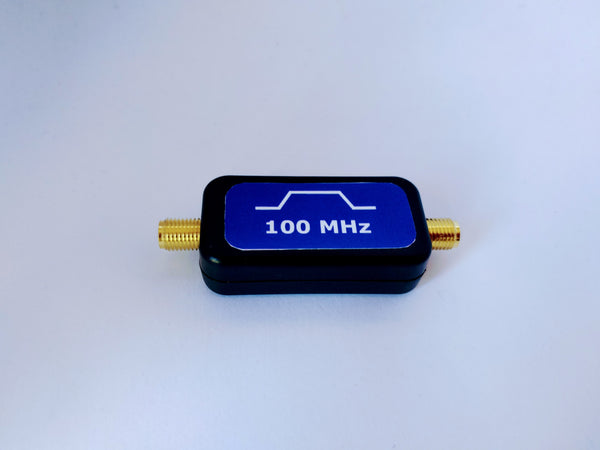
A filter centered at 100 MHz and covering the 88 to 118 MHz window passes these signals cleanly while attenuating everything outside it, protecting your receiver's front end from the strongest and most common interference sources in the VHF region.
Insertion loss at 100 MHz is 2.5 dB. The passband spans roughly 88 to 118 MHz, covering the full FM broadcast allocation and the lower portion of the VHF aeronautical band in a single part. Signals below 78 MHz are attenuated by 10 dB or more, rejection increases progressively above 120 MHz, reaching approximately 28 dB at 200 MHz. Maximum RF input is +30 dBm (1 Watt), high enough for transmit-path use as well as receive-path filtering.
Operating range is -40°C to +85°C. The filter is passive and draws no power.
APPLICATIONS:
- SDR and software-defined radio setups tuned to the FM broadcast or VHF airband range, particularly with wideband dongles that admit significant out-of-band content without filtering
- FM broadcast reception systems requiring rejection of AM broadcast, HF, and other sub-88 MHz content ahead of the receiver or LNA
- VHF spectrum monitoring covering the 88–118 MHz range
- 100 MHz reference signal cleanup: signal generators and frequency reference oscillators commonly output at 100 MHz; this filter attenuates harmonics and spurious outputs before the reference feeds downstream equipment
- Ham radio and amateur VHF work near the FM broadcast and lower VHF region
- RF test bench setups requiring a clean 100 MHz bandpass characteristic for characterization or calibration
ATTENUATION TABLE
| Frequency | Attenuation |
|---|---|
| 50 MHz | >20 dB |
| 78 MHz | 10 dB |
| 88 MHz | 4 dB |
| 100 MHz (center) | 2.5 dB insertion loss |
| 120 MHz | 4 dB |
| 130 MHz | 8 dB |
| 140 MHz | 13 dB |
| 150 MHz | 17 dB |
| 160 MHz | 20 dB |
| 170 MHz | 22 dB |
| 200 MHz | 28 dB |
NOTES:
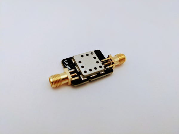
- SMA-F PCB edge mount connectors
- Maximum RF input: +30 dBm (1 Watt)
- Passive, no power required
- Operating temperature: -40°C to +85°C
For receive-only applications, placing an LNA ahead of this filter establishes your system noise figure before the filter's insertion loss reduces the signal. See our Low Noise Amplifiers for compatible front-end options.
If you need a similar filter optimised for a different center frequency or with tighter rolloff than this part provides, see our Custom RF Module Development page. We regularly develop custom VHF and UHF filters for specific bands and rejection requirements.