PRODUCT OVERVIEW
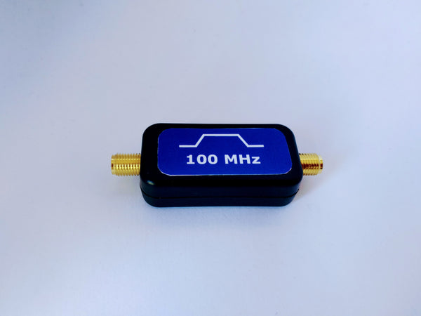
This bandpass filter passes 5170 to 7125 MHz, a 1955 MHz wide passband. That covers 5 GHz Wi-Fi from channel 36 upward and the full 6 GHz band. Insertion loss is under 1 dB.

Rejection across the 2.4 GHz ISM band is 40 dB. Harmonics are rejected too. The second harmonic of every frequency in the passband (10340-14250 MHz) is down 30 dB, and so is the third harmonic (15510-21375 MHz).
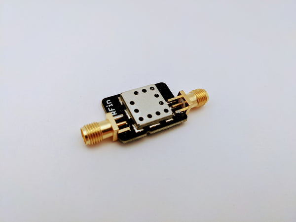
Put it in front of a receiver, SDR, or spectrum analyzer to cut 2.4 GHz energy before it reaches the front end. Put it on the output of a low-power transmitter to reduce harmonics. The maximum input power is 3 W (+34.8 dBm). It connects with SMA-F connectors.
APPLICATIONS
- 5 GHz and 6 GHz Wi-Fi. The passband covers channel 36 upward and the entire 6 GHz band used by Wi-Fi 6E and Wi-Fi 7. Use it for test benches, receiver front ends, and access point development.
- 2.4 GHz coexistence. With 40 dB of rejection across the 2.4 GHz ISM band, it protects a 5 GHz or 6 GHz receiver that shares a platform with Wi-Fi, Bluetooth, or other 2.4 GHz radios.
- Transmit harmonic filtering. It handles up to 3 W and rejects second and third harmonics by 30 dB. It fits on the output of low-power 5 GHz and 6 GHz transmitters, including 5.8 GHz FPV video and data links.
- Spectrum analyzer and SDR preselection. It keeps strong 2.4 GHz signals from overloading the input. This suits SDRs that tune up to 6 GHz.
- 5.8 GHz FPV video and unlicensed links. The 5725-5875 MHz ISM band and the common FPV video channels sit inside the passband.
- 5 cm amateur band. It covers 5650-5925 MHz for amateur microwave work.
- 5.9 GHz vehicle communications. DSRC and C-V2X operate at 5850-5925 MHz.
- Point-to-point microwave links. It suits fixed links in the 5.8 GHz and 6 GHz bands.
- System integration. The SMA connectors let you drop it inline between an antenna and a radio, LNA, or analyzer.
SPECIFICATIONS

|
Passband |
5170-7125 MHz |
|
Bandwidth |
1955 MHz |
|
Insertion loss |
Less than 1 dB |
|
Rejection, 2.4 GHz ISM band |
40 dB |
|
Rejection, 10340-14250 MHz (2nd harmonic) |
30 dB |
|
Rejection, 15510-21375 MHz (3rd harmonic) |
30 dB |
|
Maximum input power |
3 W (+34.8 dBm) |
|
Operating temperature |
-40 °C to +85 °C |
|
Connectors |
SMA-F x 2 or SMA-M + SMA-F |
|
Impedance |
50 Ω |
|
Return loss |
10-15 dB |
PLACEMENT TIP
Insertion loss under 1 dB means the noise figure penalty ahead of an LNA is under 1 dB. For the lowest system noise figure, place the filter after the first LNA. Place it first when overload is the problem.
RELATED PRODUCTS